Monday, August 30, 2010

Mini UPS System Circuit

Here's the circuit diagram of a mini low power UPS system which provides uninterrupted power supply to operate dc powered instruments of voltage rating 12V, 9V and 5V up to 1A current. The takes the load from mains without any spikes or considerable delay. The circuit involves the over charge and deep discharge of the battery for long life.

Mini UPS circuit working

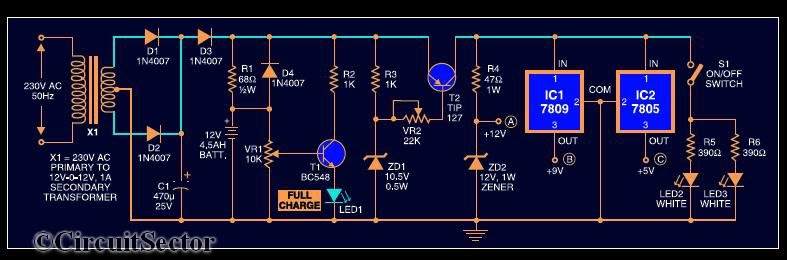
Circuit Diagram of Mini UPS System : Click  to enlarge

The UPS system consist of a 12-012 standard stepdown transformer rectified by diodes D1 & D2 and filtered by C1.When the mains power is on, diode D3 gets forward biased to charge the battery. Resistor R1 limits the charging current. LED1 indicates full charge level of 12V. When the mains supply fails, diode D4 is forward biased totake up the load without any delay. R3, ZD1 and T2 form the deep discharge cutoff circuit. For the partially charged battery, only 9V and 5V are available. Further sections of the circuit are self explanatory.

Note : 
  • Assemble the circuit on a general purpose PCB
  • Heat sinks for transistor T2 and regulator ICs (7809 and 7805) to dissipate heat are used
  • The battery used in the circuit is a 12V, 4.5Ah UPS battery

If you have any doubts, please write in the comments section.

Four Stage FM Transmitter Circuit

Here's the circuit diagram of a four RF stage FM transmitter. The stages are, very high frequency (VHF) oscillator built around a HF transistor BF494, a pre- amplifier built around transistor BF200, a driver transistor 2N2219 and a power amplifier using 2N3866.
Circuit Diagram of  4 Stage FM Transmitter: Click  to enlarge


For complete explanation about this FM transmitter circuit, Download this document.

Note :

  • This FM transmitter is only meant for educational purposes. The outdoor use is illegal.
  • Assemble the circuit on a general purpose PCB and arrange the antenna without any disruption for getting the maximum range.
  • Use a heat sink for transistor 3866.

Sunday, August 8, 2010

Fully Automatic Emergency Night Light

There are already published diagrams for automatic emergency lights but this fully automatic led base emergency light has the following special advantages.

1. Fully automatic - The name suggests its character. The emergency light charging is fully controlled and you don't have to worry about over charging of battery.

2. The emergency night light - This circuit is designed to glow leds where there no light in the room and only when there is no mains supply available. If one of them are available, the leds will not glow and the power is saved. This is achieved by using LDR and a PNP transistor.So we can plug the emergency lamp on the mains socket overnight without the fear of overcharging or waste of energy.

Related Posts with Thumbnails
 
Technology blogs & blog posts Technology blogs .CO.NR Free Domain Alitu.com - General Website Directory
Powered by Blogger