The circuit diagram shows a timer 555 based rain sound generator. The circuit requires a 9V dc power supply and can be fed from a 9V battery. The loud speaker for producing sound is of 0.5W 8ohm speaker.The circuit will readily generate a rain like sound whenever the circuit fed by a 9V supply.
Tuesday, September 21, 2010
Monday, September 13, 2010
Motion Sensor For Security Light Using PIR BS1600
Here's the circuit diagram based on PIR motion sensor module BS1600 (or BS1700) that can be used for security lighting in power saving mode.(If you could not found one in your local store , buy PIR motion sensor online).The special advantage of this motion detector circuit is it doesn't need any transformers in power supply section. The 12V DC required for feeding the motion sensor and driving relay is derived directly from the mains supply.
Sunday, September 12, 2010
7 Segment Digital Clock Circuit Using IC 5314
This circuit diagram of digital clock uses six common anode seven segment displays to show the time. It needs neither micro controllers or PIC for it's operation. It's a MM5314 IC driven digital clock operating at 50 Hz or 60 Hz, and 12 or 24 hour display format.It's very suitable for college mini projects.
 |
Circuit Diagram of 7 Segment Digital Clock : Click to enlarge |
Wednesday, September 8, 2010
Top 5 Automatic Light Circuits
Here's the list of top circuit diagrams of lighting circuits such as automatic emergency light, night light etc published on circuit sector

1. Automatic Night Lamp Circuit
This is a night lamp that turns on automatically when there is darkness in the room. Circuit is simple in design and uses very basic priciple of LDR.
2. LED Based Automatic Emergency Light
The white LED based low cost emergency light circuit diagram. six hours of battery back up - uses cheap components
3. Automatic Low Cost Night Lamp
Another redesign of automatic night lamp that reduces overall cost to build the circuit-perfect for hobbyists.
4. 20W Low cost Emergency Light
Simple emergency light circuit consist of 2 transistors, a transformer, 20 Watt fluorescent tube, 6V battery and some resistors and pots.
5. Fully Automatic Emergency Night Light
Rare circuit diagram that combines night light circuit with automatic emergency activation and
overcharge protection.
Sunday, September 5, 2010
Wireless Switch Circuit
The circuit diagram shown here is a very sensitive wireless relay switch that can be used to control the working of home appliances like flush system, hand dryer or else. The wireless switch described here needs no remote control for its working. You only want to move your hand between the infrared LED and photo transistor to control the device or load.
Monday, August 30, 2010
Mini UPS System Circuit
Here's the circuit diagram of a mini low power UPS system which provides uninterrupted power supply to operate dc powered instruments of voltage rating 12V, 9V and 5V up to 1A current. The takes the load from mains without any spikes or considerable delay. The circuit involves the over charge and deep discharge of the battery for long life.
Mini UPS circuit working
Mini UPS circuit working
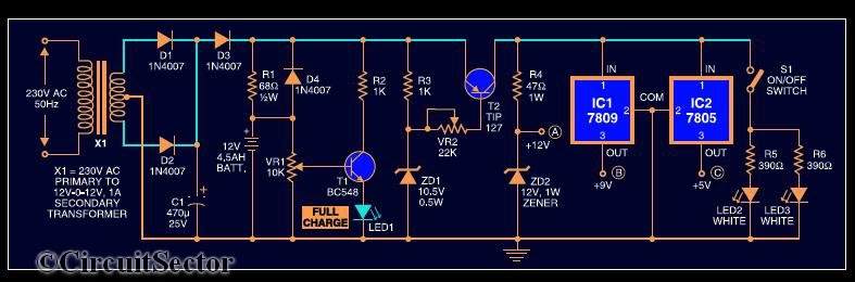 |
| Circuit Diagram of Mini UPS System : Click to enlarge |
The UPS system consist of a 12-012 standard stepdown transformer rectified by diodes D1 & D2 and filtered by C1.When the mains power is on, diode D3 gets forward biased to charge the battery. Resistor R1 limits the charging current. LED1 indicates full charge level of 12V. When the mains supply fails, diode D4 is forward biased totake up the load without any delay. R3, ZD1 and T2 form the deep discharge cutoff circuit. For the partially charged battery, only 9V and 5V are available. Further sections of the circuit are self explanatory.
Note :
- Assemble the circuit on a general purpose PCB
- Heat sinks for transistor T2 and regulator ICs (7809 and 7805) to dissipate heat are used
- The battery used in the circuit is a 12V, 4.5Ah UPS battery
If you have any doubts, please write in the comments section.
Four Stage FM Transmitter Circuit
Here's the circuit diagram of a four RF stage FM transmitter. The stages are, very high frequency (VHF) oscillator built around a HF transistor BF494, a pre- amplifier built around transistor BF200, a driver transistor 2N2219 and a power amplifier using 2N3866.
 |
| Circuit Diagram of 4 Stage FM Transmitter: Click to enlarge |
For complete explanation about this FM transmitter circuit, Download this document.
Note :
- This FM transmitter is only meant for educational purposes. The outdoor use is illegal.
- Assemble the circuit on a general purpose PCB and arrange the antenna without any disruption for getting the maximum range.
- Use a heat sink for transistor 3866.


