Here's the circuit diagram of a mini low power UPS system which provides uninterrupted power supply to operate dc powered instruments of voltage rating 12V, 9V and 5V up to 1A current. The takes the load from mains without any spikes or considerable delay. The circuit involves the over charge and deep discharge of the battery for long life.
Mini UPS circuit working
Mini UPS circuit working
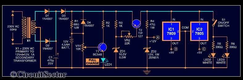 |
| Circuit Diagram of Mini UPS System : Click to enlarge |
The UPS system consist of a 12-012 standard stepdown transformer rectified by diodes D1 & D2 and filtered by C1.When the mains power is on, diode D3 gets forward biased to charge the battery. Resistor R1 limits the charging current. LED1 indicates full charge level of 12V. When the mains supply fails, diode D4 is forward biased totake up the load without any delay. R3, ZD1 and T2 form the deep discharge cutoff circuit. For the partially charged battery, only 9V and 5V are available. Further sections of the circuit are self explanatory.
Note :
- Assemble the circuit on a general purpose PCB
- Heat sinks for transistor T2 and regulator ICs (7809 and 7805) to dissipate heat are used
- The battery used in the circuit is a 12V, 4.5Ah UPS battery
If you have any doubts, please write in the comments section.

Custom Search

5 comments:
If something is explained by circuit diagrams then it becomes easy to understand each and everything.Hope to make some UPS system like this.
With the continuous development of science and technology, UPS performance getting better and better MTBF getting longer and longer working hours, increasing the reliability of machine. UPS batteries do a good job in the maintenance of consumables has become particularly important.
No fuses? :P
this is just what i was looking for! Thank you!
68 ohms series to bat to be reduced to 47 ohms to increase the charging current to 345ma to reduce the charging time to keep the bat in tip top condition and it is also safe since the charging current is below 1/10 of the bat ah.
Regards V.Sambath kumar.
I would also suggest you to add a series resistor to the base of T1 to safe gaurd the transistor while varing the pot VR1 since the full voltage will flow to the base when the pot reaches the top end. Regards V.Sambath kumar
Post a Comment