It's easier to generate DC from AC mains supply using a transforme and some diodes but the difficult part comes when we need to regulate the supply to feed sensitive devices such as mobile phones. Here's a versatile DC to DC coupler that 'll give you regulated fixed dc output voltages like 5V to charge mobile phone, 12V for external hard drives etc. You may use a 19V laptop adapter to route various voltages such as 5V , 6V, 12V from it.
Wednesday, January 29, 2014
Monday, December 2, 2013
LM317 Constant Current Battery Charger Circuit
The LM317 is an adjustable three-terminal positive-voltage regulator which can be used as a constant current source for battery charging. This regulator IC is capable of supplying 1.5 A over an output-voltage range of 1.25 V to 37 V.
Thursday, November 28, 2013
Simple UPS Circuit For Cordless Phones
This circuit diagram of UPS is designed to use with a cordless telephones that cannot be operated during power failure. Since the ups is only meant for telephone, it's output power is limiter to 1.5W. This ups circuit is economical and can be assembled on a general purpose PCB.
Monday, August 30, 2010
Mini UPS System Circuit
Here's the circuit diagram of a mini low power UPS system which provides uninterrupted power supply to operate dc powered instruments of voltage rating 12V, 9V and 5V up to 1A current. The takes the load from mains without any spikes or considerable delay. The circuit involves the over charge and deep discharge of the battery for long life.
Mini UPS circuit working
Mini UPS circuit working
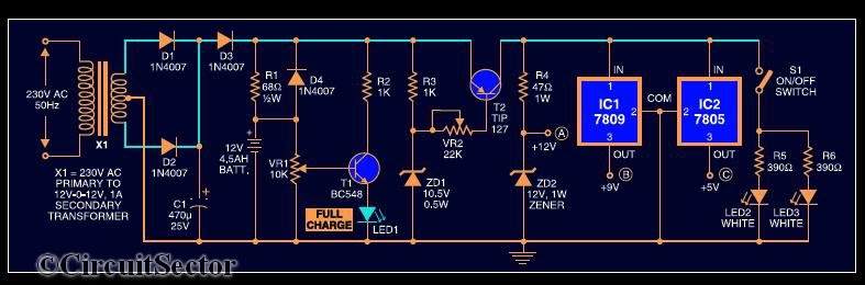 |
| Circuit Diagram of Mini UPS System : Click to enlarge |
The UPS system consist of a 12-012 standard stepdown transformer rectified by diodes D1 & D2 and filtered by C1.When the mains power is on, diode D3 gets forward biased to charge the battery. Resistor R1 limits the charging current. LED1 indicates full charge level of 12V. When the mains supply fails, diode D4 is forward biased totake up the load without any delay. R3, ZD1 and T2 form the deep discharge cutoff circuit. For the partially charged battery, only 9V and 5V are available. Further sections of the circuit are self explanatory.
Note :
- Assemble the circuit on a general purpose PCB
- Heat sinks for transistor T2 and regulator ICs (7809 and 7805) to dissipate heat are used
- The battery used in the circuit is a 12V, 4.5Ah UPS battery
If you have any doubts, please write in the comments section.
Friday, May 21, 2010
Convert Single Power Supply into Dual
We already know that the circuits using opamp will only work on dual power supply. What is actually a dual power supply? For example, usual 12V Dc means that it contains supply wires of 0 and 12V. But in the case of a dual supply, it contains 3 wires 0,-12,+12. When we check the potential difference between the +12 and -12 wires using a multimeter, it may display you about 24V dc. In normal cases, a dual power supply system consist of a center tap transformer, positive voltage regulator and a negative regulator etc. But here this circuit avoids such things from the system and uses a single LM380 IC. We get dual supply at the output whenever we give a DC voltage to it.
Sunday, May 9, 2010
USB Power Booster Circuit
Most of the peripherals that interface with PC uses USB port . The computers power supply circuit of SMPS will be designed to maintain constant power to all computer parts only. however we connect external peripherals to PC that requires significantly large power, USB power shortage will occur result in a instability of PC.when too many devices are connected simultaneously, there is a possibility of power shortage. Therefore an external usb power amplifier or source has to be added to power the external devices.